The Sierpinski Antenna

The Sierpinski Antenna |
|

A Sierpinski dipole
fed by means of a coaxial taper balun was built to measure the radiation
patterns. The following plot displays,
from left to right and top to down, the full 3D patterns at 2 GHz, 4 GHz,
8 GHz and 16 GHz, i.e., at each of the four upper bands. The most
remarkable feature of that plot is the strong similarity among patterns.
The behavior is clearly distinct from that of a classical single-band
antenna which modifies its radiating properties when changing the operating
wavelength.
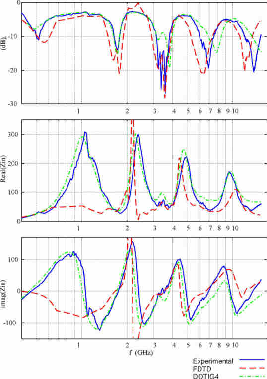
Measured and computed (FDTD, DOTIG4) input parameters of the Sierpinski monopole. From top to down, input return-loss, resistance and reactange vs. log-frequency. Five bands (return-loss minimums) are clearly distinguished. Bands are spaced by a factor of 2, the same scale-factor relating the several fractal iterations. |
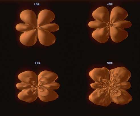
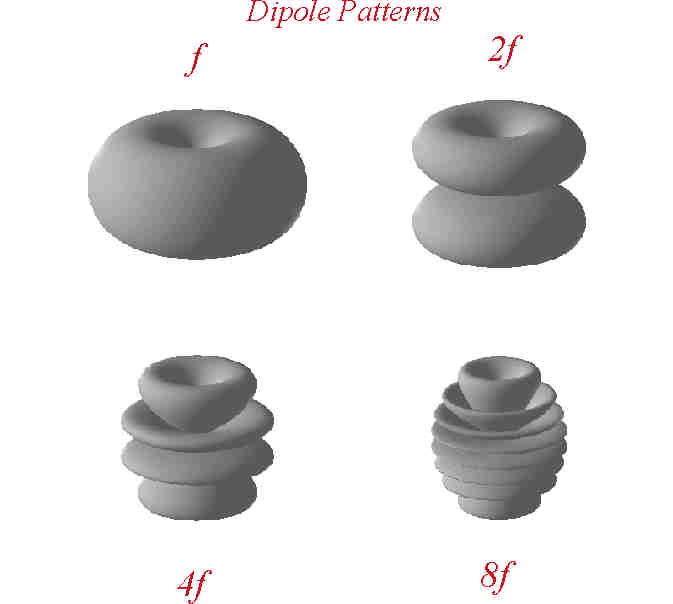
The meaured Sierpinski Dipole radiation patterns at the four upper bands. Compare the results with the same patterns for a linear dipole. |
![]()